Read This

Friday, May 31, 2013

Homemade Internal / External Threading Tool


I originally posted this on the madmodder buletin board a few years ago after I discovered how well this design worked for me. (Original Post) I wanted to share it with other HSM's as an affordable and easy approach to making an internal threading tool. Some criticism was received about clearance angles, and the heat treating, but many who have invested the time to make it were pleasantly surprised with the quality of threads they were able to produce. Anyways, I'm bringing the original post to my own blog to live for eternity...

Here's the start of the original thread:

So, yeah, I dont know if this is a new thing or not, but I've never seen another tutorial for making this type of tool anywhere so far, so here goes.

I will show you a simple way to make a threading tool completely on your lathe that can do both external as well as internal threads. I have many pictures of the process, and there's a .pdf of the actual tool with all the critical dimensions that you can download.

First off, i looked for quite some time at buying an internal threading tool that uses inserts, but the cost was rather prohibitive. Not to mention that they tell you that you need different inserts for different pitch ranges. BS I say. I'm not spending hundreds on pro tool holders and inserts. I don't need to do production threading, so I can't justify the purchase. So I came up with this idea. A machinist friend told me that it would undoubtly not work since the design lacks some clearance angles. Being a bit hard headed, I made one anyways. That was 2 years ago, and that original threading tool just failed last week, hence this article. (my bad, broke the tip off not stopping soon enough...)

The steel bar used for this is called drill rod here in Canada. It can be purchased almost anywhere. Bolt supply stores will have it, and steel dealers will know of it. It's sold in 3' lengths here. I'm not sure of the exact composition, but it's similar to O1 tool steel, I'm told. Anyways, it's stringy to work on the lathe, and not the nicest stuff for other processes, but when it's done and hardened, it's a great tool material.

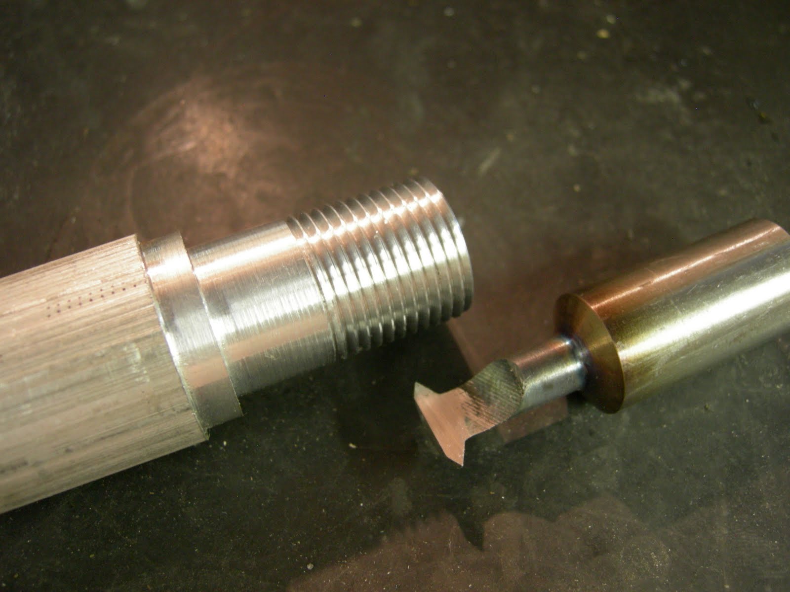
Step 1, get some drill rod that matches your boring tool holder diameter. Here I'm using 5/8". (the drawing shows 1/2", but use any size you want...) Square a T style insert to the workpiece. The edges of this tool will form the v in your threads, so take your time making sure it's good n square.

Step 2, layout the shoulder line. You don't really need to do this, make it as long as you want.

Step 3, turn the OD down to whatever you want to start with. I used 1/2" because this tool will be used on large internal threads, 2 inch and over. The smaller you make the tool, the smaller the internal threads you can make.

Step 4, Turn the undercut shaft. Keep this as short as possible, just like short stout borring tools, this follows the same idea.

 Step 5, Make the point. Use the side of the insert to make the sides nice and flat.

Step 6, Part it off.

So that's it for the turning. You should break all the sharp edges here, and face the ends of the tool flat if they aren't already.

On to the milling. This is the first time that I've done the milling part in the lathe, but it worked OK so I will show you what I did here.  Normally, I would set up the mill, clamp the tool in a vise and mill away the material, but this worked OK. Make sure everything is tight, I had some vibration when I was doing this, and the toolholder actually turned, which is not cool to see when you are hogging off material.

So, put your 1/2 finished tool in your boring tool holder. Make sure it's clamped down tight.

I used a 1/2" 4FL endmill for this, but you can use whatever you have laying around.

I adjusted the height of the threading tool to be cut manually. I started high and took a few light cuts, then just kept lowering the tool by hand, making sure the QC tool post wedged in hard each time, at each height. You can work this anyway you want. It didn't take but a few minutes and I had all the material I wanted removed.

Not the nicest machining but hey, it worked ,especially if you only have a lathe.


So that concludes the machining, that took you about 15 minutes right?  :beer:

Now the hard part, or should I say the hardeneing part? Regardless, it really easy with this steel. Heat to glowing orange, quench in water. Done. Check by trying to file. If you CAN file it's not hard, do the steps again. If the file bounces off, Good job! :beer:

Step 1, get a can full of water, a propane torch, and hold your tool with some visegrips as shown here:
 (Pistachio cans make the tool harder, that's why i use them)

Step 2, fire up the torch to high and get the tip of the tool bright orange.
Step 3, be quick as you quench the entire tool and the visegrips and your hand in the can of water, try to cool the piece as fast as cosmicly possible. This will give the best chance of making the tool hard.

Step 4, try to file part of your now hard tool. Do this on an edge that isn't important, because if you didn't get it hard, you don't want to screw up one of the critical edges right?

If the tool is adequately hard the file will not do anything. Stop now or risk destroying your file. (you should use an old file anyways...)

So if it's hard, all you have left to do is hone the top face of the tool. This is the only surface you sharpen, never try to hone the sides or you will change the angle.

(Note: There was great discussion about this on the original post, and I agree with the comment that at this point, the tool should be tempered back from full hard to ensure toughness as well as hardness. When I made these tools for threading aluminum, it didn't seem necessary, but proper form would be to temper. To do this, polish the tool so that it's bright, you need to do this to be able to see the tempering color. Now very carefully heat the cutting end of the tool. What you are looking for is for the color of the cutting tip to turn straw yellow, this is the first color that it will start turning when heated. Here's the trick, just before it turns yellow, stop heating. If it looks like you got it too hot and it's going through the colors, quench it to stop. I will do a better write up of this procedure someday.)

Just setup the tool in your boring tool holder and thread away!
Comments are always welcome!

Here's a link to the drawing of the tool. Adjust to suit your needs!

BD-LatheTools.pdf

Paul

Wednesday, May 29, 2013

Still drillin!

Seems like such a waste sometimes.  Drilling out 3/4" round bar to 5/8" id, but that's the drill!If you just can't get the right size pipe you make your own. 

This is some 12L14 round bar that I had laying around for just a job like this. This is a very free machining grade of steel, so drilling 3" through these bars was a breeze. 

These are suspension crush tubes for the inboard, lower, rear a-arms. (whew, that's a mouthful) There was nothing in there, so the plastic bushing took all the stress. They are completely hammered out now, I will do it right this time. 
 

Thursday, May 16, 2013

Chinese Checkers!

We had a blast one night on Lac LaRonge lake playing Chinese checkers after a long day of snowmobiling. The problem was that after several cocktails, the marbles on the stamped steel game board would mysteriously move to different positions with a slight bump of the table. I thought there has to be a better way to do this...

So I came up with game pieces that look like this. A peg that goes into a hole. Ingenious right...


So now for the game board. I had some surplus black UHMW, 1" plate in the shop, so that's what I cut the first board out of. I didn't like the result, and it took forever to debur, and still looked bad. Oh well, this board will be good for camping.


So off to WindsorPlywood I went in search of a nicer material to use. They had a sale on Jatoba shorts at only $8/board foot. That's a great deal, but they were all narrow boards, so I bought one, jointed and planed it, and this is what it looked like after lamination. The grain matched very nicely.


So on to machining of this piece. I used the CNC router to cut all the cavities, as well as put the rounds on the bottom of the parallelograms.Machining took about an hour.


Meanwhile, I was hard at work on the lathe making the 60 aluminum pieces required. Whew, that was alot of pieces, but I had it down to a science after the first 10. I used the ball turner I made to create the entire piece. I would form a piece on one end of aluminum round bar, flip the bar over, make another piece, then cut each piece off using the band saw. Repeat. It took about 5 minutes per piece. When they were all ready, I annodized them and gave sets of 10 pieces different colors.

After a good sanding, I finished the board with 4 coats of wipe on polyurethane applied with a foam brush. I love this finish, so easy, and looks incredible. 

That's all folks!

If you want the .pdf drawing and .dxf file of the game board, let me know. 


Hot end of extruder

Here's the more or less finished end of the filiment extruder. Not sure how well it will work, but plastic is on the way, so i will find out soon.  The heater is 230 watt and can heat the melt chamber up to 200C pretty easy, about 8 minutes. The white plates are some teflon i had laying around. Probably a bad choice for heat isolation. I dont want it melting back to the feed screw, so i may need some heat transfer behind the heater. We will see.It is however, a great material for the end of the auger screw to ride on.

An aluminum sleeve was turned from 1 1/2" round bar to fit both the heater and the black pipe. It was then slit down the middle so that the pipe clamp on the heater will squeeze the sleeve onto the pipe also. An M6x1 threaded hole was added to the sleeve for mounting the type K thermocouple. 

I dry tested this setup and the teflon seems to do a good job of isolating the heat of the hot tube to the auger assembly.  

Next job is to make the base plate the the whole system will sit on. I would really like to enclose everything but the hopper opening and the hot end, but that will be for another day.

Friday, May 10, 2013

Mods for SSR output

Here's a shot of the little temp controller guts. The ebay auction description was way off. First off, its 220vac, which caused a slight bump, I had to make a temporary plug just to test the unit. Second,  it is not  directly connectable to the solid state relay. The controller is basically a switch, which would require another power supply to activate the solid state relay (SSR).   After a bit of testing and investigation,  it was determined that since the SSR requires a 12vdc signal and the internal relay on the controller needs 12vdc to activate, I simply wired the controller to put out the relay voltage directly to the output terminals. Whalla. SSR ready. I had to cut one of the traces on the controller board. See pics.
I tested it in full heater/measure mode and it worked fine. Neat little controller anyways, especially for a whopping 18 bucks. I see that there a lot of guys playing around with this controller, probably because it's super cheap. There is a way to get into the internal settings and change a few settings if you so desire. My little test tonite having it control a pipe heater worked well. Hardly overshot at all, and kept a nice constant temp on the item being heated.
Add these 2 jumpers to put 12VDC out on the temp controller

Extruder gear train test

After buying the window motor, getting it home, and discovering the rpm of it was much faster than expected, I realized that a single speed reduction was not going to be sufficient to get the speed down low enough for the auger in the filiment extruder (about 1 rpm) Going with a 2 stage reduction using belts or chains would be a bit messy and complicated so I decided to use gears instead, a perfect job for the 3d printer.

First off was to discover the diametral pitch of the gear that was already on the window motor. It measures to be a 16DP, but it must have a special form, becuase 16DP was much to fine. Turns out a 12DP is a very good fit. Here's the tooth configuration:
Motor: 9 tooth to idler gear 48 tooth, idler gear 10 tooth to auger gear 48 tooth. So the total reduction is 48/9 x 48/10 = 25.6:1


The window motor is rated at 12VDC and I will be varying the input to get the right speed for the plastic extrusion, but at 2VDC (about as slow as it would reliably run) the output was 10RPM exactly, so the slowest speed I will be able to run is 10/25.6 = .39RPM. I will run some tests and see what the max speed I will be able to turn the auger.


Anywho, with all the maths aside, I designed the gears in Solidworks with 2 configurations, one with a plain hub for the auger, and the other configuration has the 10T gear on top of the 48T gear. Exported the STL's, sliced it up in slicer and printed them. They took about 2:20 each to print. I had to print them on a 4 1/2" square raft to keep them sufficiently stuck down to the print bed for the duration of the print. Trimming the raft was done with lexan scissors and an xacto knife. The shaft holes were bored on the lathe to ensure that they were concentric and of course the correct diameter.

Next came the issue of making mounts for both the idler and the motor. Idler first. I knew what I wanted, so the design work was quick, although the first itteration of the pillow block was much too flimsy. The second was beefed up substantially, and is the one shown in the pictures. I inserted a bearing in each side of the pillow block (excellent fit I may add, with no post op from the printing). The jack shaft was turned out of some 12L14 steel rod and grooved for an e-clip on the outside of each bearing.

The motor mount proved to be a bit more tricky. I took my laptop out to the garage so I could design it as I went. The one shown works, but I don't like the mounting points, and it's a bit flimsy. I will be designing tis mount and the pillow block to be a single piece. That should give me lots of strength and options for mounting to the base of the machine. 

Here's a shot of the gear in Solidworks.