First off was to discover the diametral pitch of the gear that was already on the window motor. It measures to be a 16DP, but it must have a special form, becuase 16DP was much to fine. Turns out a 12DP is a very good fit. Here's the tooth configuration:
Motor: 9 tooth to idler gear 48 tooth, idler gear 10 tooth to auger gear 48 tooth. So the total reduction is 48/9 x 48/10 = 25.6:1
The window motor is rated at 12VDC and I will be varying the input to get the right speed for the plastic extrusion, but at 2VDC (about as slow as it would reliably run) the output was 10RPM exactly, so the slowest speed I will be able to run is 10/25.6 = .39RPM. I will run some tests and see what the max speed I will be able to turn the auger.
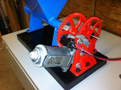
Anywho, with all the maths aside, I designed the gears in Solidworks with 2 configurations, one with a plain hub for the auger, and the other configuration has the 10T gear on top of the 48T gear. Exported the STL's, sliced it up in slicer and printed them. They took about 2:20 each to print. I had to print them on a 4 1/2" square raft to keep them sufficiently stuck down to the print bed for the duration of the print. Trimming the raft was done with lexan scissors and an xacto knife. The shaft holes were bored on the lathe to ensure that they were concentric and of course the correct diameter.
Next came the issue of making mounts for both the idler and the motor. Idler first. I knew what I wanted, so the design work was quick, although the first itteration of the pillow block was much too flimsy. The second was beefed up substantially, and is the one shown in the pictures. I inserted a bearing in each side of the pillow block (excellent fit I may add, with no post op from the printing). The jack shaft was turned out of some 12L14 steel rod and grooved for an e-clip on the outside of each bearing.
The motor mount proved to be a bit more tricky. I took my laptop out to the garage so I could design it as I went. The one shown works, but I don't like the mounting points, and it's a bit flimsy. I will be designing tis mount and the pillow block to be a single piece. That should give me lots of strength and options for mounting to the base of the machine.
Here's a shot of the gear in Solidworks.

No comments:
Post a Comment